|
|
Rapid Prototyping — Ruggedization Design for Military and Industrial Applications
Over the years, some aspects of designing rugged computers using COTS components have remained the same, while other areas have greatly changed. Here's the latest on design and manufacturing of ruggedized systems for harsh environment applications, including shock and vibration, temperature, protection from dirt and dust, and EMI/RFI shielding
By Steve Travis
Chassis Plans has been a long-time provider of ruggedized computer equipment for military and industrial applications for over 18 years. Over the years, some aspects of designing rugged computers using COTS components have remained the same, while other areas have greatly changed.
This paper discusses how Chassis Plans designs and manufactures its ruggedized systems for harsh environment applications. Below we cover the following topics: shock and vibration, temperature, protection from dirt and dust, and EMI/RFI shielding as it relates to our product offerings.
When starting any new project, Chassis Plans collects as much technical detail as possible; information such as where and how the product will be deployed, operated, and stored (from an environmental standpoint), and what the product will be used for (from a performance and security stand point). This helps determine what type of computer components are required and to what level the system needs to be ruggedized. The design aspect can change greatly depending on the customer's requirements — i.e., ground-based, wheeled-vehicle, aircraft and shipboard applications all have their own unique requirements.
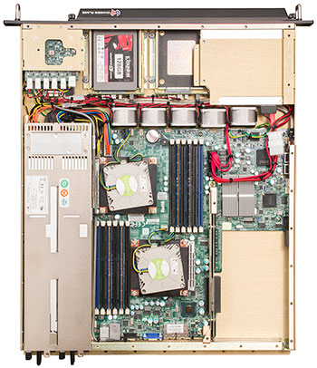
 Utilizing its vast design library, Chassis Plans has access to thousands of existing designs that cover the gamut of shapes, sizes and configurations, many that have been MIL-STD certified. Utilizing its vast design library, Chassis Plans has access to thousands of existing designs that cover the gamut of shapes, sizes and configurations, many that have been MIL-STD certified.
Our in-depth product knowledge and system designs all stem from working with customers to overcome design challenges and incorporating lessons learned with each new design. In many cases, this allows Chassis Plans to leverage a qualified existing design for new product development without having to start from "ground-up".
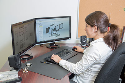
By using SolidWorks 3D CAD software for mechanical design work, new or updated designs can be created and validated virtually before any metal is manufactured, saving valuable time and money.
SHOCK AND VIBRATION
Enclosure Construction
To address shock and vibration, we can look back to several customer projects that helped to fine tune our design process regarding shock and vibration events.
On one specific project for the US Navy, Chassis Plans knew the design was to be tested to MIL-S-901D, Grade A (now defined in MIL-DTL-901E). By understanding the environmental design parameters and knowing the design concerns of integrated COTS hardware, our designers set out to create an enclosure to pass this very intensive test procedure. Simply put, throughout a very high shock event, the computer was required to continue to operate and the enclosure is required to keep its structural integrity without having any pieces or parts come loose from the system that may injure personal within that area.
Utilizing designs that had been previously tested as well as field deployed gave us a great starting point. From there our engineers determined which, if any, components would require additional reinforcements such as heavy heat sinks, components that required further stabilization, and a review of cable routing to ensure there were clean cabling paths to prevent cable tension and chaffing as well as
to ensure proper air flow. Additionally, internal shock isolators were added at strategic locations to protect sensitive equipment.
 Lastly, a review of the front and rear panels of the system were reviewed to ensure that no system parts or components have the potential to break loose during a high shock event. The enclosure utilizes a milled aluminum front panel for strength and system integrity. Power and reset switches are installed behind a sealed front door to prevent the system from accidently shut down. Lastly, a review of the front and rear panels of the system were reviewed to ensure that no system parts or components have the potential to break loose during a high shock event. The enclosure utilizes a milled aluminum front panel for strength and system integrity. Power and reset switches are installed behind a sealed front door to prevent the system from accidently shut down.
This design also uses locking hardware throughout the enclosure and captive hardware to ensure fasteners not fall free from the system and become lost.
On the rear panel, an extension bracket was added to the back of the enclosure to help support the cable assemblies that would be attached to the rear I/O of the unit. This allowed for external cable assemblies to be secured to the rear of the enclosure, while providing clean cabling service loops, removal of any stress on the rear I/O connectors, and to ensure no cabling will come loose during high shock and vibration events.
The Chassis Plans engineering team worked closely with the project team from the US Navy. Each side collaborated through the design process, sharing drawings and prototyping system components until the final designed was established. The result was a rugged 4U computer that was tested to and passed MIL-S-901D Grade A. The video of the 901D Barge test can be seen here: https://www.youtube.com/watch?v=swAWpmboN64
Rugged Systems Integration (a turn-key system)
Chassis Plans often provides its customers with a basic rugged computer platform, but in many applications the customer will be required to add additional hardware or software to the system prior to delivering the final product to their customer. As a value-add to our customers, Chassis Plans will integrate additional hardware and or load software into a rugged platform, thus providing the customer with a truly a "turn-key" product, all assembled in one location.
Customers may require additional I/O to communicate with their software, sometimes this could be an off-the-shelf I/O board, or other times an add-in board developed by the customer. Chassis Plans prefers to install these cards during the assembly process at our factory (whenever possible), to ensure installed ruggedization, proper cabling/power routing and that the board receives the required cooling it needs. Not only is this a further enhancement to the system itself, but it is one less thing a customer needs to worry about during their manufacturing process.
Additionally, software can be handled in the same manner. Working with the customer, Chassis Plans can create a revision-controlled software Golden Image. This software can be loaded with the computers Operating System and is one more benefit to the customer, getting them one step closer to project completion.
EXTENDED TEMPERATURE OPERATION
When working with COTS components within a ruggedized platform, heating and cooling of these components can become quite a challenge. Most COTS components have not been designed with extended temperature operation in mind. That said, we know certain COTS materials can operate at extended temperature for a duration of time without decreasing performance or damaging components. When gathering the needed project environmental data, the first question we will ask is "What is the required operating and storage temperature range?" along with "How long the unit is required to operate or be stored at those levels?".
Below we list three of the most common Operational temperature ranges and how we address each:
LEVEL 1 - Standard Temperature Range
Most Chassis Plans customers require a 0°C to 50°C operating temperature range. At this level any Chassis Plans configuration will operate indefinitely with no impact on the lifespan of the product.
 LEVEL - 2 Enhanced Temperature Range LEVEL - 2 Enhanced Temperature Range
The second operational temperature range is a requirement for -20° to 60°C.
While a stock configuration can operate at extended temperatures for a short period of time, if greater operational time is required modifications may be necessary.
We start with the review of each system component. The manufacturer's product thermal characteristics data are reviewed, the component itself is examined, and potential upgrades such as larger heat sinks, etc. are identified and implemented. We review how the components are installed within the enclosure and possible ways to route additional cooling to "hot spots" via cooling fan relocation or additional air ducting. Lastly, cooling fans can be upgraded to increase air flow and modifications can be made to the thermal management system to increase fan speed rotation. In this scenario, a standard rugged chassis is tuned to the specific requirements of a system with higher demands.
To address low temperature operation, initializing warm-up heaters may be added to the system. For cold start operations, the power would be applied to the internal heating elements and fans allowing warm air to preheat the system before start-up takes place.
LEVEL 3 - Extended Temperature Range
The third operational temperature range is -40 to 85C. As mentioned above, a computer system can operate at these levels for a very short duration (hours). If the system is required to be stored and or operational during extended periods of time, then a very different component strategy is needed, moving away from commercial grade components.
Chassis Plans can specify components certified to operate at the -40 to 85C storage and operating temperatures. As an example, the power supply for these units is solid state design. Likewise, the system hard drives are solid state and are industrial grade. The computers system board differs from a comparable commercial unit by upgrading board level components like crystal oscillators, relays, capacitors, resistors, diodes, and magnetics to better endure the extreme temperature requirements. There are a handful of low power Intel CPU's, screened for -40 to 85C storage and operating temperatures available. The selection of a proper CPU is a combination of customer performance requirements as well as environmental considerations.
Additionally, depending on the environmental conditions and components selected, the enclosure structure itself is generally a "sealed" design. An integrated heat sink, built into the enclosure sidewall, transfers internal heat to the outside of the chassis.
DUST AND SAND
Many of Chassis Plans customers are software designers that often are surprised to learn after winning a military contract award that a rugged computer able to support harsh environment operation is required to run their software. This was such the case for a recent project. The customer, a developer of persistent surveillance software, had won a large contract from the US Army. During testing of the system their generic IT-grade computers began to fail at the test site. The systems were becoming clogged with dirt and dust, eventually causing the systems to overheat and lock up. The customer was given 12 weeks to come up with a rugged solution or lose the multi-million-dollar contract.
Chassis Plans quickly evaluated the environmental and system performance requirements and began work on designing a ruggedized computer system that could meet all requirements under a very short timeline. A ruggedized 5U (HPC) computer enclosure was designed that utilized many of our common design criteria, such as tight-fitting seams and joints, solid front panel with integrated air filter and a light "over pressure" to keep air pushing out of all openings. The biggest challenge to the design was managing the heat generated by the system all the while maintaining proper air-filtration.
The system, a dual CPU Xeon platform with (4x) NVidia Tesla cards generated a tremendous amount of internal heat. To comply with the project environmental filtration requirements (basically talcum powder) required much denser air filters than on our stock system configurations. While this prevented dust from entering the system, it also lowered the amount of air flow for cooling down an already hot system. Ultimately our engineering team developed a successful filtered cooling solution by upgrading cooling fans, ducting air flow, and fine-tuning adjustments to the Syscool thermal management system. The product was delivered to the customer in time to pass and win the contract.
EMI/RFI SHIELDING
Another area of environmental concern is with EMI/RFI shielding. There are times where our computers are installed in areas with higher than normal EMI/RFI emissions requirements. Inherently Chassis Plans enclosures are designed with this type of shielding in mind. Features like tight and overlapping joints and seams, honeycomb vents for air intake and exhaust, as well as optional upgrades for additional EMI filters and enhancements.
Beyond what has been described, modifications can be made to further enhance a rugged computer's EMI/RFI shielding.
 As an example, Chassis Plans developed a ruggedized system for a telemetry company that was mounting the unit into an aircraft. This system required shielding above and beyond our standard shielding options. The rear panel of the computer is traditionally the weak spot for EMI/RFI emissions due to the I/O connectors and add in board slot locations as well as unshielded external cabling. As an example, Chassis Plans developed a ruggedized system for a telemetry company that was mounting the unit into an aircraft. This system required shielding above and beyond our standard shielding options. The rear panel of the computer is traditionally the weak spot for EMI/RFI emissions due to the I/O connectors and add in board slot locations as well as unshielded external cabling.
To remedy this problem for this application, our engineering team developed a "dog house" rear enclosure. The traditional I/O connectors are enclosed within a sealed metal enclosure and the I/O connections are re-routed to MIL-CIRCULAR shielded connectors. The air exhaust for the enclosure was additionally filtered as well. External cable assemblies were manufactured from shielded materials and terminated into MIL-CIRCULAR shielded connectors. The provided system was then tested to and passed MIL-STD-461 and select DO-160 EMI testing.
In conclusion, there are many ways to protect COTS hardware in harsh military and industrial environments. The challenge is a balance between providing required computer system performance along with the deployed environmental characteristics as well as keeping the platform cost effective.
Also, as shown in the examples, it becomes a true partnership between Chassis Plans and its customers to rapidly develop the best solution for each customer and project. For additional information or to speak with a dedicated Chassis Plans Program Manager please contact us at (858) 571-4330 for more information.
Steve Travis serves as Technical and Commercial Adviser for Chassis Plans where he is responsible for marketing activities focusing on ruggedized computer and LCD display products for military and industrial applications. Steve has more than 24 years' experience as an entrepreneur, in technical sales, product management, marketing communications and leadership roles. Steve currently resides in San Diego, California
|


